Introduction
The PAR-sensor measures the section of the light spectrum that converts the plant into growth (photosynthesis). PAR stands for Photosynthetic Active Radiation, and includes the light spectrum between 400 and 700 nm.
 |
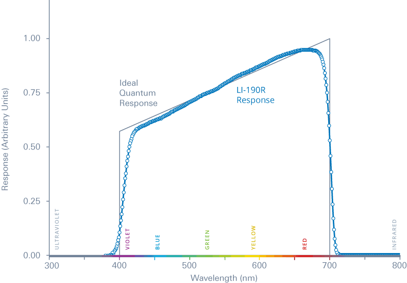 |
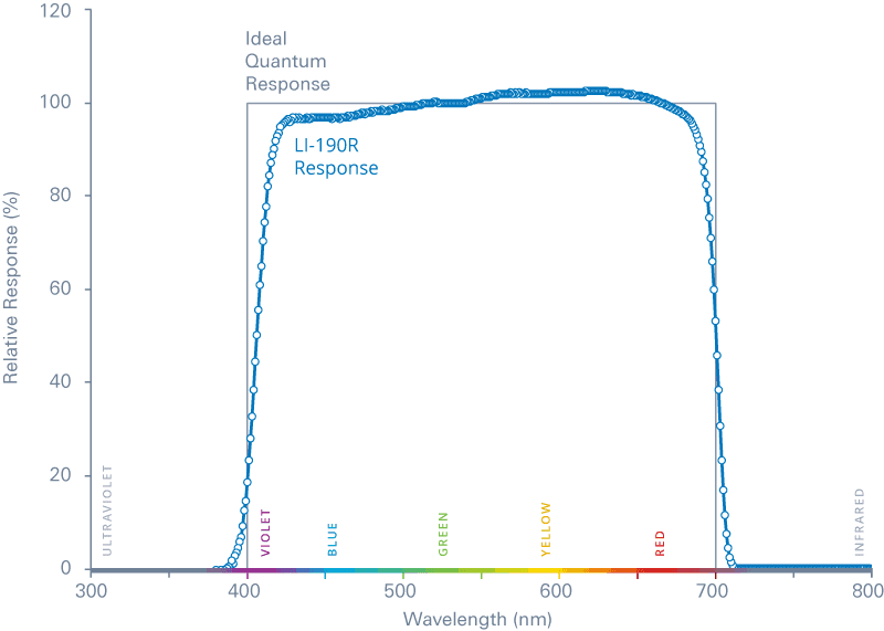
| The figure above shows the LI-190R response and the ideal quantum response in photon units | The figure above shows the LI-190R response and the ideal quantum response in energy units |
The PAR sensor can be mounted outside or inside the greenhouse. When mounted inside the greenhouse, the sensor can be mounted above or below the grow lights, depending on how it is to be integrated with the lighting control.
Connecting the PAR sensor
- Connect the LI-COR PAR sensor to the UTA amplifier input.
- Pass the LI-COR sensor cable through the UTA cable gland nearest the 2-terminal (blue/black & brown/light green) connection block. Loosen the gland nut if necessary.
- Connect the LI-190R PAR sensor signal wire (brown) to brown/light green terminal in the amplifier
- Connect both the LI-190R signal return wire (blue) and shield to blue/black terminal in the amplifier.
- Connect the UTA amplifier to the Compass.
- The black common wire from the UTA needs to be connected to the field ground of the input as well as the 0 VDC of the DC power supply. These should have been connected in the Compass panel during production but make sure no one disconnected it. If a UI8 module was added, make sure that the UI8 field ground is also connected to the field ground terminals in the panel.
- The red power wire from the UTA needs to be connected to the 24VDC power supply reserved for field devices.
- The green signal output wire needs to be connected to the corresponding universal input.
Setting PAR sensor calibration values in Compass
Each PAR sensor is supplied with a calibration certificate. This calibration certificate is needed to calibrate the sensor in the Priva Compass. If you cannot find your certificate, you can go to Licor's website and download it. The PAR sensor needs to be cleaned every three months and recalibrated every 2 years after field deployment.
Each PAR sensor is also supplied with a UTA (Universal Transconductance Amplifier) since the signal from the sensor itself is too low to be measured by the Compass. The amplification of the UTA can be determined on the label on the side of the UTA

Calibrating the PAR sensor
Using the calibration value from the certificate, use the table below to determine the proper multiplication factor. The multiplication factor is dependent on the model of amplifier.
The type of amplifier can be determined based on the label on the side of the amplifier.
| Calibration value | ||
| 125 umol/s/m2 per microamp | 73 | 104 |
| 126 umol/s/m2 per microamp | 72 | 103 |
| 127 umol/s/m2 per microamp | 72 | 103 |
| 128 umol/s/m2 per microamp | 71 | 102 |
| 129 umol/s/m2 per microamp | 71 | 101 |
| 130 umol/s/m2 per microamp | 70 | 100 |
| 131 umol/s/m2 per microamp | 70 | 99 |
| 132 umol/s/m2 per microamp | 69 | 99 |
| 133 umol/s/m2 per microamp | 69 | 98 |
| 134 umol/s/m2 per microamp | 68 | 97 |
| 135 umol/s/m2 per microamp | 68 | 96 |
| 136 umol/s/m2 per microamp | 67 | 96 |
| 137 umol/s/m2 per microamp | 67 | 95 |
| 138 umol/s/m2 per microamp | 66 | 94 |
| 139 umol/s/m2 per microamp | 66 | 94 |
| 140 umol/s/m2 per microamp | 65 | 93 |
| 141 umol/s/m2 per microamp | 65 | 92 |
| 142 umol/s/m2 per microamp | 64 | 92 |
| 143 umol/s/m2 per microamp | 64 | 91 |
| 144 umol/s/m2 per microamp | 63 | 90 |
| 145 umol/s/m2 per microamp | 63 | 90 |
| 146 umol/s/m2 per microamp | 62 | 89 |
| 147 umol/s/m2 per microamp | 62 | 89 |
| 148 umol/s/m2 per microamp | 61 | 88 |
| 149 umol/s/m2 per microamp | 61 | 87 |
| 150 umol/s/m2 per microamp | 61 | 87 |
| 151 umol/s/m2 per microamp | 60 | 86 |
| 152 umol/s/m2 per microamp | 60 | 86 |
| 153 umol/s/m2 per microamp | 60 | 85 |
| 154 umol/s/m2 per microamp | 59 | 85 |
| 155 umol/s/m2 per microamp | 59 | 84 |
| 156 umol/s/m2 per microamp | 58 | 83 |
| 157 umol/s/m2 per microamp | 58 | 83 |
| 158 umol/s/m2 per microamp | 58 | 83 |
| 159 umol/s/m2 per microamp | 57 | 82 |
| 160 umol/s/m2 per microamp | 57 | 81 |
| 161 umol/s/m2 per microamp | 57 | 81 |
| 162 umol/s/m2 per microamp | 56 | 80 |
| 163 umol/s/m2 per microamp | 56 | 80 |
| 164 umol/s/m2 per microamp | 56 | 79 |
It is possible that the PAR sensor measures a small amount of light (less than 4 µmol/s¹ m²) at night. This can be corrected by entering an offset in the ‘ light sensor zero calibration offset’ found in the configuration menu.
Specifications
LI-190R Specifications
Universal Transconductance Amplifier Specifications
| Supply Voltage | 5–24 VDC, single supply, at least 1 volt higher than full scale out |
| Supply Current: | less than 1mA |
| Gain accuracy: | ±0.2% on factory preset range (± 0.5% all ranges ) |
| Voltage output in darkness | <4 millivolts |
| Supply Voltage variation effect | : less than 0.01% per Volt |
| Response | 2 milliseconds (special versions available) |
| Temp range | -30 °C to +70 °C / -22°F to +174°F |
| Tempco: | less than 0.01% per °C / less than 0.005% per °F |
| Output impedance: | 1000Ω ±1% |
| Enclosure | NEMA 4 gasketed white polycarbonate |
Article numbers
| 3779237 | LI-COR LI-190-R-BL-5 PAR sensor with 0.4 amplifier |
| 3779239 | LI-COR LI-190-R-BL-5 PAR sensor with 0.28 amplifier |